Wednesday, 8 October 2014

06:22 - No comments

What is an antenna port and their mapping?

The LTE standard defines what are known as antenna ports. These antenna ports do not correspond to physical antennas, but rather are logical entities distinguished by their reference signal sequences. Multiple antenna port signals can be transmitted on a single transmit antenna (C-RS port 0 and UE-RS port 5, for example). Correspondingly, a single antenna port can be spread across multiple transmit antennas (UE-RS port 5, for example).The LTE standard defines what are known as antenna ports. These antenna ports do not correspond to physical antennas, but rather are logical entities distinguished by their reference signal sequences. Multiple antenna port signals can be transmitted on a single transmit antenna (C-RS port 0 and UE-RS port 5, for example). Correspondingly, a single antenna port can be spread across multiple transmit antennas (UE-RS port 5, for example).

The 3GPP TS 36.211 LTE standard defines antenna ports for the downlink. An antenna port is generally used as a generic term for signal transmission under identical channel conditions. For each LTE operating mode in the downlink direction for which an independent channel is assumed (e.g. SISO vs. MIMO), a separate logical antenna port is defined. LTE symbols that are transmitted via identical antenna ports are subject to the same channel conditions. In order to determine the characteristic channel for an antenna port, a UE must carry out a separate channel estimation for each antenna port. Separate reference signals (pilot signals) that are suitable for estimating the respective channel are defined in the LTE standard for each antenna port. FIG 1 shows the antenna ports defined in the LTE standard in Releases 8,9 and 10.


The way in which these logical antenna ports are assigned to the physical transmit antennas of a base station is up to the base station, and can vary between base stations of the same type (because of different operating conditions) and also between base stations from different manufacturers. The base station does not explicitly notify the UE of the mapping that has been carried out, rather the UE must take this into account automatically during demodulation (FIG 2). As far asThe way in which these logical antenna ports are assigned to the physical transmit antennas of a base station is up to the base station, and can vary between base stations of the same type (because of different operating conditions) and also between base stations from different manufacturers. The base station does not explicitly notify the UE of the mapping that has been carried out, rather the UE must take this into account automatically during demodulation (FIG 2).


Let us consider antenna ports used for PDSCH allocations since they probably have the most variations. Initially, the 89600 VSA's LTE demodulator supported only analysis of PDSCH transmitted on Antenna Ports 0, (0 and 1), (0, 1, 2), or (0, 1, 2, 3). These ports are considered C-RS antenna ports, and each port has a different arrangement of C-RS resource elements. Various configurations are defined that use these C-RS antenna ports, including 2- or 4-port Tx Diversity and 2-, 3-, or 4-port Spatial Multiplexing.


Then beamforming support was added and single-layer PDSCH allocations transmitted on Port 5 could be analyzed. The LTE demodulator has since been enhanced to support the LTE Release 9 which added Transmission Mode 8--Dual-Layer Beamforming (i.e. beamforming + spatial multiplexing)--where PDSCH is transmitted on Antenna Ports 7 and 8 (note that single-layer beamforming in Rel 9 can also use port 7 or port 8 in addition to port 5). In Rel 10 of the standard, the new transmission mode 9 (TM9) added up to 8-layer transmissions using Ports 7-14. TM9 is supported by the LTE-Advanced demodulator.

As Ports 0-3 are indicated by the existence of C-RS, so Ports 5 and 7-14 are indicated by the UE-specific Reference Signal (UE-RS). The following is a table that summarizes the various PDSCH mappings that can be used along with the corresponding reference signal and antenna ports.

In a MIMO or Tx Diversity configuration, each C-RS antenna port must be transmitted on a separate physical antenna to create spatial diversity between the paths. Single-layer beamforming, on the other hand, is accomplished by sending the same signal to each antenna but changing the phase of the each antenna's signal relative to the others. Since the same UE-RS sequence is sent from each antenna, the 89600 VSA can compare the received UE-RS sequence with the reference sequence and calculate the weights that were applied to the antennas to accomplish the beamforming.

Multi-layer beamforming adds some complexity to beamforming by transmitting as many UE-RS sequences as there are layers to allow demodulation of each layer's PDSCH data. The UE-RS sequence for each antenna port is orthogonal to the others, either in time/frequency domain or in the code domain. This can be thought of as beamforming of each layer independently. N-layer beamforming is an extension of dual-layer beamforming and supports up to 8 data layers with the ability to beamform each layer separately.


Saturday, 4 October 2014

Scheduling operation in LTE

Basic Scheduling Operations:
- Purpose
* Efficient SCH(Data) Resources Assignments
- Consideration
* Traffic Volume, QoS (Buffer Status, Priority…)
* Channel Condition
- Scheduling Interval
* Dynamic Scheduling by MAC : One TTI (1ms : One Sub-frame)
* Semi-Persistent for VoIP : Multiple TTIs by RRC
- Resource Assignment : PRBs & Associated MCS

Scheduling information: DCI PDCCH


DCI


Resource Assignment
- Per UE # PRBs Assignment
* Channel Dependent Resource Allocation
  •User Assignment based on Channel Quality
- CQI / MCS / TBS


CQI Reporting for Scheduling
Reporting modes


- In time : Periodic (PUCCH/PUSCH) & Aperiodic (PUSCH)
- In Frequency
• Wide-band CQI : 4 bit
• Differential Sub-band CQI : 2 bit (Sub-band CQI – Wideband CQI)
• Differential Spatial CQI : 3bit for MIMO

Schedulers in LTE

DL Scheduling
DL MAC Scheduler


MAC Layer

it would be almost impossible to explain everything about MAC but i have tried to simplify MAC by diagram.
lets start to read diagram first and see what MAC does? i have taken diagram from 3GPP TS:36.321 and modified according to me to simplify MAC


MAC Layer
- Mapping between logical channels and transport channels;

Query_1: what kind of channel used for mapping in UE/eNodeB?
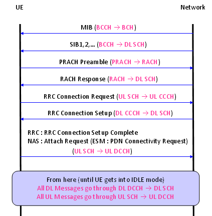
UE    -->  Logical channel (CCCH, DCCH and DTCH) <--> Transport Channel (RACH and UL-SCH)
CCCH, DCCH, DTCH are all mapped to UL-SCH.
There is a special channel called 'RACH', but this does not have any corresponding logical channel.
eNodeB -->  Logical channel (PCCH, BCCH, MCCH, MTCH, CCCH, DCCH and DTCH) <--> Transport Channel (PCH, BCH, MCH and DL-SCH)
PCCH (Logical Channel) is mapped only to PCH (Transport channel).
Some BCCH is mapped to BCH and Some BCCH is mapped to DL-SCH. Do you know which one is which ? BCCH for MIB is mapped to BCCH and BCCH for SIB is mapped to DL-SCH.
DL-CCCH, DCCH, DTCH are all mapped to DL-SCH.

Query_2: What channel modified or what is not modified by MAC?

from Diagram:
i) All the logical channes (PCCH, BCCH, CCCH, DCCH, DTCH) goes through MAC layer. (too simple reading ? -:)
ii) It seems that PCCH does not get manipulated by MAC in any special way. It just looks as if it is by passing MAC process. It does not use HARQ procedure meaning 'no retransmission' mechanism being used.
iii) CCCH, DCCH, DTCH all go through the same procedure (Prioritization, Mux/DeMux, HARQ).
iv) Some BCCH goes through HARQ, but some BCCH does not go through HARQ. Do you know which BCCH go through HARQ and which does not ? BCCH for MIB does not go through HARQ, but BCCH for SIB go through HARQ. (But this HARQ is a little different from normal HARQ that we know of.. It does not expecting any ACK/NACK response from the reciever.. but perform 'retransmission' based on a predefined rule).
v) Random Access process orignated within MAC layer, it does not have the correspoding logical channel. (This may apply to Msg1, Msg2 of RACH procedure.. Msg3,4,5 involves RRC layer intervention as well).

Query_3: what kind of information carry channel?
Logical Channels : Type of information
Transport Channels : How the information is transferred


Try to correlate each messages in the call flow with the channel mapping. And the try to correlate this mapping with the diagrams described above. Ask a couple of questions to yourself, e.g which of these message use HARQ ? Which message is carried by a 'Common' channel and which messages are carried by a 'Dedicated' channel.

- Multiplexing of MAC SDUs from one or different logical channels onto transport blocks (TB) to be delivered to the physical layer on transport channels;
- de-Multiplexing of MAC SDUs from one or different logical channels from transport blocks (TB) delivered from the physical layer on transport channels;

Query_4: How data multiplex/de-mux happen?

- Scheduling information reporting;

Query_5: How scheduling report?

- error correction through HARQ;

Query_6: How error correction happen through HARQ?

- Priority handling between UEs by means of dynamic scheduling;
- Priority handling between logical channels of one UE;
- Logical Channel prioritization

Query_7: how logical channel prioritize

- Transport format selection.

Query_8: how mac select transport format?
Data is sent from the physical layer to the MAC layer in the form of transport channels. The MAC layer is responsible for mapping the transport channels onto logical channels and transmitting the data up to the RLC layer, and thereverse - receiving data on logical channels from the RLC layer and mapping that data onto transport channels for the physical layer. On those channels, MAC layer is also responsible for segmenting long messages from higher layers into blocks, and reassembling blocks from the physical layer into messages for the higher layers.
MAC layer is also responsible for selecting the transport formats used on the transport channels, and distinguishing between different UEs using the common channels.


Every TTI (1ms) a set of Transport Blocks is transferred from the MAC to the Physical layer. The data will be coded and split into blocks to be sent out every 10ms radio frame.
Data from MAC could be sent in a single large Transport Block or in a set of smaller Transport Blocks. The latter approach allows the number of blocks (and hence the data rate) to be varied more simply in each TTI.

Mac Procedure
- Random Access

Query_9: How RACH happen?

- DL-SCH Data Transfer

Query_10: How DL-SCH data transfer?

- UL-SCH Data Transfer

Query_11: How UL-SCH transfer?

MAC PDU:

MAC Control Element

RNTI


Friday, 3 October 2014

RNTI

RNTI stands for Radio Network Temporary Identifier. As the name implies, it is a kind of Identification number. Normally we use indentification number to differntiate one thing from all other similar things.
Followings are the brief summary of RNTIs being used in LTE. i hope this diagram will clear you about RNTI what kind of RNTI? what type of RNTI? what are the value for RNTI? what is the mapping of RNTI?


Who issues these RNTI ?
Network issues RNTI.

Exactly what does RNTI do for each of those radio channel ? The detailed process differs with the types of RNTIs, but generally speaking all of these RNTI is used to scramble the CRC part of the radio channel messages. It implies that if UE does not know the exact RNTI values for each of the cases, it cannot decode the radio channel messages even though the message reaches the UE intact.


One of the most common questions that I got about RNTI is "There are a lot of different types of RNTI and I don't see any RNTI information on DCI or Higher layer signaling message. Then how can PHY layer know which RNTI it has to use to decode a data ?". The answer is "MAC or Layer 1 controller would instruct PHY on which RNTI it has to use". Then a next questions comes out. "How MAC or Layer 1 controller would know which RNTI to be used ?". There is no explicit algorithm for this, MAC/L1 controller needs to figure it out "based on context". For example, if it is at the subframe where SIB is transmitted, it would instruct PHY to use SI-RNTI. if UE is in connected mode, it may instruct to use C-RNTI, TPC RNTI etc.

How each of RNTI is used ?
Following is the quotes from 3GPP specification showing how RNTI is used for various cases.. for the exact details, you should see the specification but this partial quote would give you a rough idea of the usage of RNTI.

From 3GPP TS:36.212

5.3.3 Downlink control information
  • A DCI transports downlink or uplink scheduling information, or uplink power control commands for one RNTI. The RNTI is implicitly encoded in the CRC. 
5.3.3.1.3 Format 1A
  • Format 1A is used for random access procedure initiated by a PDCCH order only if format 1A CRC is scrambledwith C-RNTI
  • For distributed VRB: .. if the format 1A CRC is scrambled by RA-RNTI, P-RNTI, or SI-RNTI
5.3.3.2 CRC attachment
  • This section explain in detail on how CRC is scrambled by RNTI. Following is the summary of this process. As you see, RNTI is used to scramble CRC bits of PDCCH.

MAC PDU Formats

1. A MAC PDU primarily consists of the MAC header and the MAC payload. (it's very simple and general to say)

2. The MAC header is further composed of MAC subheaders, while the MAC payload is composed of MAC Control Elements, MAC SDUs and padding.


•Each MAC PDU corresponds to a single Transport Block (TB)
•There is one sub-header for each MAC Control Element in the PDU and each MAC SDU in the PDU

3. Each MAC subheader consists of a Logical Channel ID (LCID) and a Length (L) field.
4. The LCID indicates whether the corresponding part of the MAC payload is a MAC Control Element, and if not, to which logical channel the related MAC SDU belongs.
5. The L field indicates the size of the related MAC SDU or MAC Control Element.


MAC header consists of multiple sub-headers
•One sub-header for each Control Element, MAC PDU or Padding
•Each sub-header is 1 or 2, 3 bytes in length
–[R/R/E/LCID]: Used for fixed length MAC SDUs and MAC Control Elements
–[R/R/E/LDID/F/Length]: Used for variable length MAC SDUs


MAC Control Elements are used for MAC-level peer-to-peer signalling, including delivery of BSR information and reports of the UE’s available power headroom in the uplink, and in the downlink DRX commands and timing advance commands. For each type of MAC Control Element, one special LCID is allocated. When a MAC PDU is used to transport data from the PCCH or BCCH logical channels, the MAC PDU includes data from only one logical channel. In this case, because multiplexing is not applied, there is no need to include the LCID field in the header. In addition, if there is a one-to-one correspondence between a MAC SDU and a MAC PDU, the size of the MAC SDU can be known implicitly from the transport block size. Thus, for these cases a headerless MAC PDU format is used as a transparent MAC PDU.

MAC Control Element

Seven Control Elements are defined 
4 for DL
•Timing Alignment (8bits): Sent to provide initial and periodic time synchronization to the UE for UL
•DRX Command (8 bits): Initiates discontinuous reception mode at UE
•UE Contention Resolution Identity (48bits): Used during RACH procedure to resolve possible contention b/w multiple UEs trying to simultaneously access the network 
•MCH Scheduling Information MAC Control Element
3 for UL
•UE Buffer Status Reports (8 or 24bits): Reports UE buffer occupancy for UL scheduling
•UE Power Headroom (8 bits): Reports UE transmit power compared to maximum or if the UE is currently power limited
•C-RNTI (16 bits): Identifies a UE when sending information over CCCH

12:43 - 4 comments

How Multiplexing and Logical Channel Prioritization happen in LTE?

The multiplexing and logical channel prioritization is left to the eNodeB implementation, for the uplink the process by which a UE creates a MAC PDU to transmit using the allocated radio resources is fully standardized; this is designed to ensure that the UE satisfies the QoS of each configured radio bearer in a way which is optimal and consistent between different UE implementations. Based on the uplink transmission resource grant message signalled on the PDCCH, the UE has to decide on the amount of data for each logical channel to be included in the newMAC PDU, and, if necessary, also to allocate space for a MAC Control Element.
The Logical Channel Prioritization procedure is applied when a new transmission is performed.
One simple way to meet this purpose is to serve radio bearers in order of their priority. Following this principle, the data from the logical channel of the highest priority is the first to be included into the MAC PDU, followed by data from the logical channel of the next highest priority, continuing until the MAC PDU size allocated by the eNodeB is completely filled or there is no more data to transmit.
RRC controls the scheduling of uplink data by signalling for each logical channel: priority where an increasing priority value indicates a lower priority level, prioritisedBitRate which sets the Prioritized Bit Rate (PBR), bucketSizeDuration which sets the Bucket Size Duration (BSD).
The UE shall maintain a variable Bj for each logical channel j. Bj shall be initialized to zero when the related logical channel is established, and incremented by the product PBR × TTI duration for each TTI, where PBR is Prioritized Bit Rate of logical channel j. However, the value of Bj can never exceed the bucket size and if the value of Bj is larger than the bucket size of logical channel j, it shall be set to the bucket size. The bucket size of a logical channel is equal to PBR × BSD, where PBR and BSD are configured by upper layers.
Although this kind of priority-based multiplexing is simple and favours the highest priorities, it sometimes leads to starvation of low-priority bearers. Starvation occurs when the logical channels of the lower priority cannot transmit any data because the data from higher priority logical channels always takes up all the allocated radio resources.
To avoid starvation, while still serving the logical channels according to their priorities, in LTE a Prioritized Bit Rate (PBR) is configured by the eNodeB for each logical channel. The PBR is the data rate provided to one logical channel before allocating any resource to a lower-priority logical channel.
In order to take into account both the PBR and the priority, each logical channel is served in decreasing order of priority, but the amount of data from each logical channel included into the MAC PDU is initially limited to the amount corresponding to the configured PBR. Only when all logical channels have been served up to their PBR, then if there is still room left in the MAC PDU each logical channel is served again in decreasing order of priority.
In this second round, each logical channel is served only if all logical channels of higher priority have no more data for transmission. 
In most cases, a MAC Control Element has higher priority than any other logical channel because it controls the operation of a MAC entity. Thus, when a MAC PDU is composed and there is a MAC Control Element to send, the MAC Control Element is included first and the remaining space is used to include data from logical channels. One exception to this rule occurs when a UE transmits the first RRC message to a target cell during a handover procedure – in this case, a MAC Control Element such as a BSR has lower priority than SRBs. This is because it is more important to complete the handover procedure as soon as possible than to inform the eNodeB of the UE’s buffer status; otherwise, the data transfer interruption time would be longer and the probability of handover failure would increase due to the delayed signalling.

Example:
LTE MAC multiplexing 
LTE MAC multiplexing by way of example. First, channel 1 is served up to its PBR, channel 2 up to its PBR and then channel 3 with as much data as is available (since in this example the amount of data available is less than would be permitted by the PBR configured for that channel). After that, the remaining space in the MAC PDU is filled with data from the channel 1 which is of the highest priority until there is no further room in theMAC PDU or there is no further data from channel 1. If there is still a room after serving the channel 1, channel 2 is served in a similar way. 


Logical Channel Prioritization
The UE shall perform the following Logical Channel Prioritization procedure when a new transmission is performed:
- The UE shall allocate resources to the logical channels in the following steps:
- Step 1: All the logical channels with Bj > 0 are allocated resources in a decreasing priority order. If the PBR of a radio bearer is set to “infinity”, the UE shall allocate resources for all the data that is available for transmission on the radio bearer before meeting the PBR of the lower priority radio bearer(s);
- Step 2: the UE shall decrement Bj by the total size of MAC SDUs served to logical channel j in Step 1
NOTE: The value of Bj can be negative.
- Step 3: if any resources remain, all the logical channels are served in a strict decreasing priority order (regardless of the value of Bj) until either the data for that logical channel or the UL grant is exhausted, whichever comes first. Logical channels configured with equal priority should be served equally.
- The UE shall also follow the rules below during the scheduling procedures above:
- the UE should not segment an RLC SDU (or partially transmitted SDU or retransmitted RLC PDU) if the whole SDU (or partially transmitted SDU or retransmitted RLC PDU) fits into the remaining resources; 
- if the UE segments an RLC SDU from the logical channel, it shall maximize the size of the segment to fill the grant as much as possible;
- UE should maximise the transmission of data.
The UE shall not transmit data for a logical channel corresponding to a radio bearer that is suspended (the conditions for when a radio bearer is considered suspended are defined in [8]).
For the Logical Channel Prioritization procedure, the UE shall take into account the following relative priority in decreasing order:
- MAC control element for C-RNTI or data from UL-CCCH;
- MAC control element for BSR, with exception of BSR included for padding;
- MAC control element for PHR;
- data from any Logical Channel, except data from UL-CCCH;
- MAC control element for BSR included for padding.

Query: The significance of Bucket size duration(BSD) in logical channel prioritization.
Ans: The BSD is basically used to set the maximum amount of pending data allowed for a logical channel, with respect to the prioritization checks. The more data a logical channel has, the higher its priority tends to be, but it can't exceed the value set by Prioritized Bit Rate x Bucket Size Duration. (e.g. 100 kbps x 1 second = 100 kbits). This keeps a logical channel experiencing a very high burst of data from taking over the transmission and blocking out a lower rate channel. See 36.321, section 5.4.3.1.

The bucket size duration indicates how much time for transmitting uplink data of a logical channel by using the prioritized bit rate until the bucket size is reached, value in milliseconds.

For a LCID the bucket size = BSD x PBR (both are in MAC config struct) that is the maximum UL data a LCID can buffer. The first time scheduling will happen based on Token bucket model for all LCID's with different priorities. Here every LCID can send PBR amount of data.
Each LCID accumulates BSDxPBR amount of data. The rate of accumulation is PBR * tti upto BSDxPBR.
There is another counter Bj in MAC that is used to make sure that there is no starvation of lower priority LCID's.
The second time on,
If Bj > 0 then higher priority LCID can send RLC data size and reduce Bj accordingly. Other LCID's may or may not be scheduled. If Bj is negative for higher priority LCID then other LCID with lower priority are scheduled.

lRRC IEs LogicalChannelConfig
-                    LogicalChannelConfig
l                    Priority (1 to 16)
l                    PrioritisedBitRate (0kbps to 2048kbps)
l                    BucketSizeDuration (ms50 to ms1000)
l                    LogicalChannelGroup (0 to 3)